

Gas pressure regulator sizing goes wrong in both directions: too small starves the network at peak demand, too large hunts and loses accuracy at low flow. This guide gives a step-by-step procedure for sizing and selecting a gas pressure regulator, from the data and the EN 334 coefficient Cg to the checks, type and accessories, with a worked example in round numbers. It serves engineers in Saudi Arabia, the UAE, Qatar, Kuwait, Bahrain, Oman and the wider Middle East, and builds on our gas pressure regulator guide.
Key takeaways
- Size at the minimum inlet pressure and the maximum flow; check control at the minimum flow.
- In critical flow the required Cg is Q / (0.526 × Pu), with Pu in bar absolute.
- Allow about 20 % of Cg for an in-line monitor, 5 % for a built-in monitor, silencer or slam shut, plus the 10 % Cg tolerance.
- At low outlet pressures the outlet velocity, not Cg, usually decides the body size.
In this article
- Step 1: collect the sizing data
- Step 2: calculate the required flow coefficient (Cg)
- Step 3: choose the size at the minimum inlet pressure
- Step 4: velocity, noise and derating checks
- A worked example of gas pressure regulator sizing
- Step 5: type, fail mode, pressure class and accessories
- Common sizing mistakes and a selection table
- How Pietro Fiorentini can help
- Frequently asked questions
Step 1: collect the sizing data
Before opening a capacity table, record:
- Inlet pressure, minimum and maximum, gauge or absolute. Capacity is decided at the minimum; design pressure and flange class at the maximum.
- Set point and tolerance: the accuracy class (AC) and lock-up class (SG) the downstream equipment accepts.
- Flow range: peak, minimum (night, summer and winter) and growth, with reference conditions.
- Gas data: composition, relative density, temperature, dust, water and hydrogen blending.
- Protection, site and interface: fail-open or fail-close, slam-shut and relief requirements, noise limit, hazardous-area classification, ambient temperature, sand and dust, pipe size and flange standard.
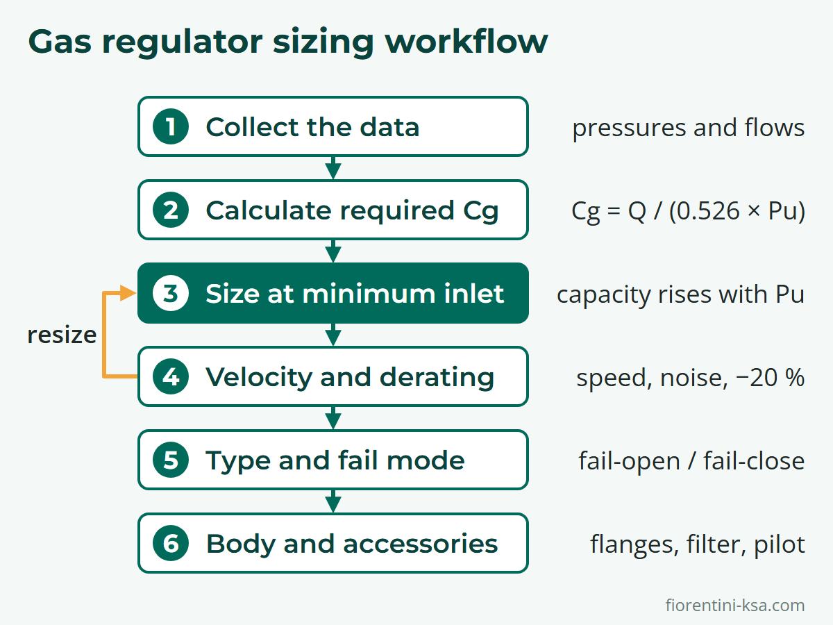
Step 2: calculate the required flow coefficient (Cg)
Each size of a regulator has one published Cg value, and Pietro Fiorentini's brochures size with Cg together with the form factor K1, following EN 334. The regulator guide linked above derives the capacity formulas. Solved for Cg, with Q as the flow in standard cubic metres per hour at 15 °C and 1 bar absolute, natural gas of relative density 0.61, and Pu and Pd as the absolute inlet and outlet pressures in bar:
- Critical flow (Pu ≥ 2 × Pd): Cg = Q / (0.526 × Pu)
- Sub-critical flow (Pu < 2 × Pd): Cg = Q / (0.526 × Pu × sin(K1 × √((Pu − Pd) / Pu))), sine in degrees
K1 comes from the datasheet; it is 106.78 for every Reflux 819 size. Two details matter: the pressures are absolute, so add about 1 bar to gauge readings, and the sine term applies only below the critical ratio, where it always raises the required Cg.
Step 3: choose the size at the minimum inlet pressure
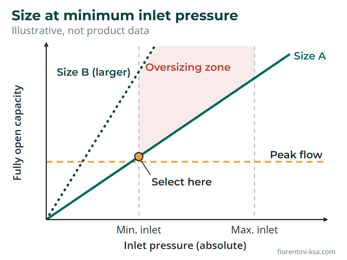
In critical flow the fully open capacity is proportional to the absolute inlet pressure, so a regulator passes the least gas when the inlet is lowest. Calculate the required Cg at the minimum inlet pressure, apply the allowances from Step 4, and select the smallest size whose published Cg is higher.
Turndown and the cost of oversizing
Turndown is the ratio of the maximum usable flow to the minimum flow still controlled within the accuracy class; datasheets quote it as a ratio (1:200 on the Dival 600 flyer) or as a minimum flow (0.1 Qmax for the Ratio Governors). Check your minimum flow against the candidate's capacity at maximum inlet pressure, when it is most oversized: a regulator working with the plug almost on the seat hunts, erodes its seat and misses its accuracy class.
Where one size cannot cover the range, split the duty over two lines, as in the pressure reducing station guide. On small lines the FT 518 offers another route: six replaceable orifices from 3/32 to 1/2 inch match the capacity to the duty without changing the body.
Step 4: velocity, noise and derating checks
A size that passes on Cg can still fail three checks.
Outlet velocity and noise. The outlet-flange speed in the brochures is V = 345.92 × (Q / DN²) × (1 − 0.002 × Pd) / (1 + Pd): V in m/s, Q in Stm³/h, DN in mm, Pd in barg. The acceptable value is a matter of local practice, set to limit erosion and noise; as one published reference, GIS/E34 for UK and Irish modules up to 7 bar inlet accepts 40 m/s in the outlet header with filtered gas. Pietro Fiorentini's silencer charts mark 85 dBA as the recommended noise limit.
Upstream pressure drops. The filter, the slam-shut valve and any in-line monitor each take a pressure drop, so Pu should be the pressure at the regulator inlet at peak flow. A dry gas filter such as the HFA-HFB can carry a clogging indicator that shows when a rising drop eats into capacity. Check also the minimum differential pressure (0.5 bar on the Reflux 819) at the lowest inlet.
Derating for accessories. When an in-line monitor sits upstream, Pietro Fiorentini's brochures reduce the Cg of the active regulator by 20 %. A monitor incorporated on the body, a built-in silencer or a built-in slam shut each lower the Cg by about 5 %, and published Cg values may vary by up to 10 % under the EN 334 acceptance criteria.
A worked example of gas pressure regulator sizing
The figures are illustrative round numbers; size a real line with the manufacturer's data or sizing program.
Data. A district station: inlet 16 to 25 barg, set point 4 barg, peak flow 3,000 Stm³/h, night flow 300 Stm³/h, filtered natural gas of relative density 0.61, in-line monitor upstream, fail-open philosophy.
Required Cg. At minimum inlet, Pu = 17 and Pd = 5 bar absolute. Since 17 ≥ 2 × 5 the flow is critical: Cg = 3,000 / (0.526 × 17) = 335. Dividing by 0.8 for the in-line monitor gives 419, and by 0.9 for the Cg tolerance about 470.
Size on Cg. In the published table of one pilot-operated family from the high–medium pressure range, the Reflux 819, Cg is 575 for 1 inch, 2,220 for 2 inch and 4,937 for 3 inch. On Cg alone the 1-inch size passes: 0.526 × 575 × 17 × 0.8 gives about 4,100 Stm³/h at minimum inlet.
Velocity check. For 3,000 Stm³/h at 4 barg the outlet-flange speed is about 330 m/s at DN 25, 82 m/s at DN 50, 32 m/s at DN 80 and 21 m/s at DN 100. Against a 40 m/s limit the 3-inch body is the first to pass: at low outlet pressures, velocity, not Cg, sets the body size.
Low-flow check. The 3-inch size has about ten times the required Cg. At the maximum inlet of 26 bar absolute its derated capacity is about 54,000 Stm³/h, so the night flow is 0.6 % of capacity, a turndown near 180:1. This is the moment to run the manufacturer's sizing program and to weigh two regulating lines, or a body with an enlarged outlet that lowers the flange velocity.
Step 5: type, fail mode, pressure class and accessories
Direct-operated or pilot-operated
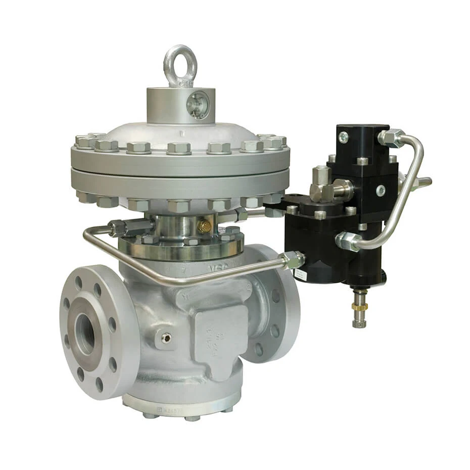
Direct-operated regulators suit small and medium flows and simple duties; pilot-operated regulators hold the set point more closely, reaching AC 1 on the Reflux 819, and cover the large sizes at city gates. See pilot-operated vs direct-operated gas regulators.
Fail mode and protection
EN 334 classifies regulators as fail-open or fail-close. Fail-open with a monitor keeps gas flowing after a failure; fail-close stops the supply. The Reval 182 offers both: fail-close with the 200/A pilot series, fail-open with the 210/A series. The Terval/A and Terval/R put the regulator, a PM/182 monitor and an SA slam shut on one body: the Terval/A is fail-open and the Terval/R is fail-close. For high-pressure lines the Terval AP takes 0.5 to 100 bar inlet. Monitor, slam-shut (EN 14382) and relief set points are covered in the guide to slam-shut, monitor and relief valves.
Pressure class, filtration and preheating
- Pressure class and connections. The design pressure must cover the maximum inlet; most station regulators offer Class 150, 300 or 600 RF or RTJ to ASME B16.5, or PN to ISO 7005. For very high inlet pressures the 1-inch Staflux Mini, a direct-operated fail-close regulator for 5 to 250 bar inlet, uses Class 1500 RF flanges or NPT threads.
- Spring or pilot range. The set point must sit inside a published range, and some accessories must be specified at order: the HP 100 slam shut, for example, cannot be retrofitted.
- Filtration. Pietro Fiorentini regulators are specified for previously filtered gas, which matters in the sand and dust of the GCC. Fit a station filter upstream, or a regulator with a built-in cartridge filter such as the Dival SQD-6, a 2-inch inlet, 3-inch outlet unit for up to 6 bar inlet and 10 to 300 mbar outlet.
- Preheating. Every bar of pressure drop cools natural gas by about 0.4 to 0.5 °C, so the 25 to 4 bar cut in the example costs around 9 °C: harmless with dry gas in a warm climate, but a deeper cut, a cold inlet or wet gas can freeze or block pilots. For the pilot circuit, the ATF anti-freeze regulator keeps the pilot supply above freezing by reducing pressure inside the main pipeline, set 3 to 4 bar above the main set point.

Common sizing mistakes and a selection table
| Mistake | Effect | Better practice |
|---|---|---|
| Sizing at maximum inlet | Starved network when inlet drops | Size at minimum inlet |
| Oversizing "to be safe" | Hunting, seat wear, poor accuracy | Check minimum flow at maximum inlet |
| Ignoring derating and velocity | Capacity short; noise, erosion | Apply Cg reductions; run the speed formula |
Duty-to-family map:
| Duty | Type | Families |
|---|---|---|
| City gate, transmission, large industry | Pilot-operated | Reflux 819 (0.8–100 bar inlet, 1–12 inch), Aperflux 851, ASX 176, Terval AP |
| Compact high-pressure duty | Direct or pilot | Staflux Mini (5–250 bar inlet, 1 inch), Dixi AP |
| District station, medium–low pressure | Pilot or direct | Reval 182 (0.2–25 bar inlet, 1–10 inch), Aperval 101, Terval/A, Terval/R, Dival 600, Dival 700, Norval |
| Commercial and small industry | Direct-operated | Dival SQD-1/2/6, FT 518, HP 100 |
| Residential service lines | Two-stage | FE (6–50 m³/h, with OPSO), FEX, NeoR |
| Burners, low-pressure networks | Governors | Governors STD, Goval, RCS 201/705, Ratio and Zero Governors |
How Pietro Fiorentini can help
Pietro Fiorentini Saudi Industry in Al Khobar supplies gas pressure regulators in all three pressure classes, from governors to 12-inch pilot-operated units. District-station models sit in the medium–low pressure range. Service regulators and governors sit in the low-pressure range. Its engineers size with Pietro Fiorentini's sizing program and run the checks described here; its services cover installation, commissioning and maintenance across Saudi Arabia, the UAE, Qatar, Kuwait, Bahrain, Oman and the Middle East.
Need a regulator sized? Send us the inlet pressure range, set point, peak and minimum flows and gas data, and our engineers will propose a size, type and configuration. Contact our engineers.
Frequently asked questions
What data do I need to size a gas pressure regulator?
Minimum and maximum inlet pressure, the set point with its accuracy and lock-up classes, peak and minimum flow, gas composition and relative density, temperatures, the required fail mode, the noise limit and the connections. Minimum inlet and peak flow set the size; minimum flow and maximum inlet check it.
What happens if a gas pressure regulator is oversized?
It works with the plug close to the seat. Small movements cause large flow changes, so the outlet pressure hunts, the accuracy class is missed and the seat erodes under high-velocity flow. Check the minimum flow against the capacity at maximum inlet, and prefer two regulating lines to one large regulator.
What is Cg on a regulator datasheet?
Cg is the flow coefficient EN 334 uses for regulators, published per size. In critical flow (absolute inlet at least twice the absolute outlet) the fully open capacity for natural gas is 0.526 × Cg × Pu in Stm³/h, so the required Cg is Q / (0.526 × Pu). Below the critical ratio a sine term with the form factor K1 reduces the capacity.
Should I choose a pilot-operated or a direct-operated regulator?
Choose direct-operated for small and medium flows where a few percent of droop is acceptable. Choose pilot-operated when the set point must hold within a tight accuracy class, when the size is large or the inlet pressure varies widely, or when a monitor and slam shut are combined on one body.
How much margin should I add when sizing a gas regulator?
Build the margin from documented allowances rather than a round safety factor: about 20 % of Cg for an in-line monitor, 5 % each for a built-in monitor, silencer or slam shut, the 10 % Cg tolerance, and the upstream pressure drops. More than that pushes the size up and worsens low-flow control.
References
- EN 334:2019+A1:2024 Gas pressure regulators for inlet pressure up to 10 MPa (100 bar) – Swedish Institute for Standards (SIS)
- EN 14382:2019 Gas safety shut-off devices for inlet pressure up to 10 MPa (100 bar) – Swedish Institute for Standards (SIS)
- EN 12186:2025 Gas pressure control stations for transmission and distribution – Estonian Centre for Standardisation (EVS)
- Reflux 819 technical brochure (sizing and Cg, gas speed, derating) – Pietro Fiorentini
- GIS/E34:2021 Pressure regulating modules with inlet pressures up to 7 bar – Energy Networks Association / IGEM
- Joule-Thomson effect in case of mixtures of natural gas and hydrogen – Danish Gas Technology Centre