

A slam shut valve is a safety device that quickly shuts off the gas flow when the pressure it monitors goes above or below a preset limit. It stays shut until someone resets it by hand. On a gas pressure regulating line it has two partners. A monitor regulator takes over if the active regulator fails open, and a small relief valve vents short pressure peaks.
Key takeaways
- A slam shut valve trips on overpressure (OPSO) or underpressure (UPSO) and reopens only by manual reset.
- A monitor regulator takes over if the active regulator fails open, so supply continues.
- A small token relief valve vents thermal expansion and minor leakage, avoiding needless slam shut trips.
- Set points typically rise from regulator to monitor, token relief and slam shut, all below the downstream limit.
In this article
- Why gas regulating stations need overpressure protection
- The layers of gas overpressure protection on one line
- How a slam shut valve works
- Monitor regulators: protection that keeps gas flowing
- Gas pressure relief valves: token or full-capacity relief
- How to stagger the set points
- Integrated or separate slam shut valve?
- Testing and maintenance
- How Pietro Fiorentini can help
- Frequently asked questions
Why gas regulating stations need overpressure protection
Downstream of a regulating station, pipework, meters and appliances are usually rated below the upstream pressure. A regulator that fails closed stops the gas, which is disruptive but rarely damaging. One that fails open can expose them to upstream pressure, which can damage piping and appliances, as the US pipeline safety agency PHMSA warns.
EN 334, the European regulator standard, classes regulators as fail open or fail close (see the gas pressure regulator guide). It leaves other failures to redundancy under EN 12186, for example a regulator with an integrated safety shut-off device, a regulator plus an in-line monitor, or a regulator plus a separate shut-off device. EN 12186:2025 sets the functional requirements for gas pressure control stations up to 100 bar. Its pressure safety system covers safety shut-off devices, monitors, safety-related electrical or electronic solutions, and venting devices.
Every layer must respect the downstream limit. The European pipeline standard EN 1594 calls it the maximum incidental pressure (MIP): the highest pressure a system may see briefly, limited by safety devices.
The layers of gas overpressure protection on one line
In flow order, a protected regulating line typically has:
- Filter, which keeps dust and welding slag away from the valves downstream.
- Slam shut valve, upstream of the regulators, so that a trip isolates everything after it.
- Monitor regulator, which takes over if the active regulator fails open.
- Active regulator, which controls the outlet pressure.
- Relief valve, on a downstream branch that vents to a safe place.
All three protective devices respond to the pressure downstream of the active regulator. An upstream monitor or slam shut therefore needs a sensing line that runs past the active regulator to the outlet pipe. The slam shut, monitor and active regulator each need their own sensing line, protected from damage. Two-line layouts, metering and preheating are covered in the gas pressure reducing and metering station guide.

PHMSA compares the three methods:
| Device | Supply after it acts | Gas vented | How the event shows |
|---|---|---|---|
| Monitor regulator | Continues | None | Only a rise in outlet pressure |
| Slam shut valve | Stops until manual reset | None | Supply stops |
| Relief valve | Continues | Excess gas | Noise and odor |
How a slam shut valve works
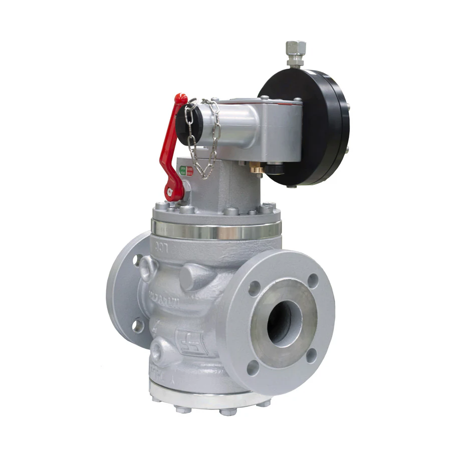
A typical slam shut valve has a spring-loaded plug held open by a latch, and a pressure switch connected to the protected pipe by a sensing line. On the SBC 782, the sensed pressure acts against a maximum-pressure spring and a minimum-pressure spring. When the pressure leaves the window set by the two springs, the latch releases and a spring drives the plug onto its seat.
Closure is fast: within 1 second on the SBC 782, and adjustable from 0.5 to 2 seconds on the HBC 975. Both can also be tripped locally or remotely, and optional micro-switches can report a trip to a control room.
OPSO and UPSO
The maximum-pressure spring sets the over-pressure shut-off (OPSO), and the minimum-pressure spring sets the under-pressure shut-off (UPSO). LPG guidance from the UK Health and Safety Executive calls them back-up protection should the regulator fail or supply pressure fall dangerously low. Depending on its pressure switch, the SBC 782 covers OPSO settings from 0.03 to 90 bar. Small service regulators such as the FEX integrate both functions.
What EN 14382 requires
EN 14382:2019+A1:2024 covers gas safety shut-off devices (SSDs) for inlet pressures up to 100 bar and sizes up to DN 400. Its functional class A closes if the pressure-detecting element is damaged or external power fails. Class B does not close on such damage, but still provides suitable and reliable protection. Both may reopen only manually. It also covers response time and the accuracy group (AG), the trip accuracy in percent of the set point. Pietro Fiorentini quotes up to AG 2.5 for the SBC 782 and AG 1 for the HBC 975.
Monitor regulators: protection that keeps gas flowing
EN 334 defines a monitor as a second regulator in series with the active regulator, normally upstream, that keeps the controlled pressure within allowable limits. Set slightly higher, it sits wide open until the active regulator fails open. It then takes control, so supply continues and no gas is vented.
An in-line monitor is a second, mechanically similar regulator upstream. An incorporated monitor, such as the PM/819 on the Reflux 819/FO, shares the valve body but has its own actuator, pilot and seat. It lowers the flow coefficient (Cg) by 5 percent. An accelerating valve, an extra pilot set above the monitor, speeds up the take-over by venting the monitor's actuator.
The weak point is alerting: usually the only sign of a take-over is a higher outlet pressure. Pressure alarms and checks of the monitor's position indicator close that gap.
Gas pressure relief valves: token or full-capacity relief
A relief valve vents gas to atmosphere when the pressure exceeds its set point, and recloses as the pressure falls. Where a monitor or slam shut handles regulator failure, the relief valve is deliberately small. This token relief vents short-lived excess pressure so the slam shut does not trip on a transient. EN 334 covers a similar built-in device, the creep (venting) relief device. The FT 518 regulator has one built in.
Typical causes are thermal expansion of gas at zero flow, pressure shocks and minor leakage at regulator lock-up. Heat matters at Gulf sites. As a rough ideal-gas estimate, trapped gas at 2 bar gauge that warms from 20 °C to 50 °C rises to about 2.3 bar gauge. The VS/AM 65 covers set ranges from 15 mbar to 7 bar, and the 1-inch VS/AM 58 is designed for pressures up to 100 bar.

Full-capacity relief is a different design choice: the valve and its vent must pass the flow of a fully failed-open regulator. US federal rules require relief stations to have enough capacity to hold pressure within set limits (49 CFR 192.201). Pilot-operated valves such as the PVS 782, rated up to 102 bar, suit these duties. But venting releases methane, and EN 12186:2025 adds measures to avoid greenhouse gas emissions.
How to stagger the set points
The devices must act in a fixed order, with gaps wider than their combined tolerances, and the slam shut must close before the MIP is reached. The UPSO trip sits below the lowest normal operating pressure. Regulator lock-up must stay clearly below the relief setting, or the relief valve will vent whenever demand stops.
For set points of 2.1 to 5 bar on a line with a monitor, slam shut and relief valve, the Reflux 819/FO technical manual gives these rules:
| Device | Setting rule | Example at 4.0 bar | Role |
|---|---|---|---|
| Active regulator | Set point (Pas) | 4.0 bar | Controls the outlet |
| Monitor | 1.1 × Pas | 4.4 bar | Takes over on failure |
| Accelerating valve | 1.2 × Pas | 4.8 bar | Speeds up the monitor |
| Relief valve | 1.3 × Pas | 5.2 bar | Vents transients |
| Slam shut OPSO | 1.4 × Pas | 5.6 bar | Closes on high pressure |
| Slam shut UPSO | Pas − 0.5 bar | 3.5 bar | Closes on low pressure |
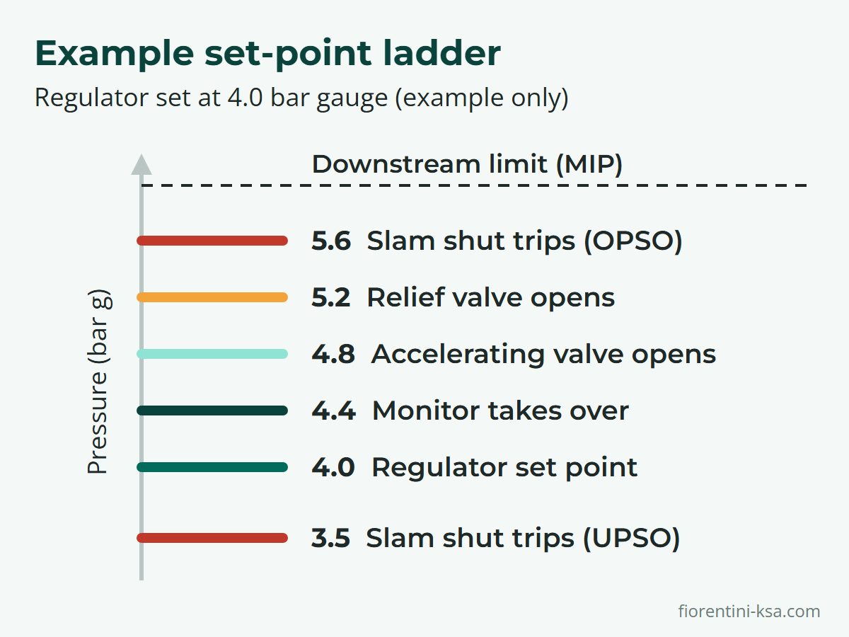
At 25 to 74 bar the manual narrows the gaps, to 1.03 × Pas for the monitor and 1.3 × Pas for the OPSO trip. Real values come from the station design.
Integrated or separate slam shut valve?
Many regulators can carry a built-in slam shut, including the Reflux 819, Aperflux 851, Norval and Dival 600. On the Reflux 819/FO it can be retrofitted in the field and lowers Cg by 5 percent. When it trips, it cuts the gas to both the regulator and its pilot. The FT 518 accepts a slam shut or an integral monitor, and the FE and FEX service regulators have OPSO built in.
Integrated designs keep the line compact, with fewer flanged joints. Separate valves can be installed alone or upstream of a regulator, and are sized for their own pressure drop. Their end-to-end dimensions follow EN 334 and EN 14382:
| Model | Design pressure | Sizes | Typical duty |
|---|---|---|---|
| SBC 782 | Up to 102 bar | Up to 10 in | Transmission, city gates, district stations |
| HBC 975 | Up to 102 bar | Up to 12 in | High-pressure transmission, power generation |
| SSX 176 | Up to 102 bar | Up to 6 in | Compact; transmission, medium pressure |
| SCN | Up to 16 bar | Up to 8 in | Medium and low pressure distribution |
| Dilock | Up to 20 bar | Up to 2 in | Distribution, commercial and industrial users |
| SBC 187, SBC Mini | Up to 250 bar | 1 in | Ultra-high-pressure, small-bore lines |
Testing and maintenance
EN 14382 relies on periodic functional checks, at intervals set by national regulations or user and manufacturer practice. Pietro Fiorentini manuals describe them:
- Slam shut trip test: apply a controlled auxiliary pressure to the pressure switch. Raise it slowly to record the OPSO trip; reset, then lower it slowly to check UPSO. Repeat at least two or three times, reconnect the sensing line, and confirm that a manual trip stops the flow.
- Tightness: with the slam shut closed, check at the downstream bleed cock that it seals.
- Monitor: open the active regulator fully by raising its setting, and confirm that the monitor holds its own set point.
- Relief valve: raise the downstream pressure with the pilot setting or an auxiliary supply, and check the opening point.
The Reflux 819/FO manual recommends trip tests at least every six months. The SBC 782 manual adds a monthly check that slam shuts and standby monitors show fully open, a half-yearly visual inspection, and new valve-seat seals at least every six years.
At Gulf sites, keep upstream filters clean, since dust fouls seats and sensing lines. Shade equipment in direct sun so it stays within its rated temperature range, typically −20 °C to +60 °C.
How Pietro Fiorentini can help
Pietro Fiorentini Saudi Industry in Al Khobar supplies the full protection set. Its valves and filters range includes slam shut valves with design pressures from 16 to 250 bar and direct- and pilot-operated relief valves. Many of its regulators offer built-in slam shut and monitor options. For critical infrastructure, its gas networks range adds HIPPS, a high-integrity pressure protection system rated up to SIL 3 (safety integrity level), and complete pressure reducing and metering stations (PRMS). The services team supports engineering, commissioning, maintenance and training.
Reviewing the protection on a regulating line? Send us the upstream and downstream pressures, flow range and gas data. Our engineers will help you select and configure each device. Contact our engineers.
Frequently asked questions
What is the difference between a slam shut valve and a relief valve?
A slam shut valve closes the line when pressure leaves its set window and stays closed until reset by hand. A relief valve vents excess gas and recloses when pressure falls, so supply continues. A slam shut contains the gas but stops supply; a relief valve keeps supply but releases gas.
What do OPSO and UPSO mean on a slam shut valve?
OPSO, over-pressure shut-off, trips the valve when the sensed pressure rises above its maximum setting. UPSO, under-pressure shut-off, trips it when the pressure falls below its minimum setting. Each function usually has its own adjustable spring, so a valve can be set for either or both.
Why does a slam shut valve need a manual reset?
EN 14382 allows safety shut-off devices to reopen only manually. A trip means that something has failed, so the line should not restart until someone has found and fixed the cause. On the SBC 782, the reset lever first opens an internal bypass to equalize the pressure across the plug, then re-latches the mechanism.
What is a monitor regulator?
A monitor is a second regulator in series with the active regulator, usually upstream, and set slightly higher so it stays wide open. If the active regulator fails open, the monitor takes control at its own set point, so supply continues without venting. It can be separate or built into the regulator body.
How often should a slam shut valve be tested?
Follow national regulations, the operator's procedures and the manufacturer's manual, since EN 14382 leaves the interval to them. As a reference, the Reflux 819/FO manual recommends trip tests at least every six months. The SBC 782 manual adds a monthly check that the valve shows fully open.
References
- EN 14382:2019+A1:2024 Gas safety shut-off devices for inlet pressure up to 10 MPa (100 bar) – DIN Media
- EN 334:2019+A1:2024 Gas pressure regulators for inlet pressure up to 10 MPa (100 bar) – Swedish Institute for Standards (SIS)
- EN 12186:2025 Gas pressure control stations for transmission and distribution – Functional requirements – Swedish Institute for Standards (SIS)
- SBC 782 slam shut valve brochure – Pietro Fiorentini
- Reflux 819/FO technical manual MT103 – Pietro Fiorentini
- Guidance Manual for Operators of Small Natural Gas Systems – US DOT PHMSA