

A gas pressure reducing station takes natural gas from a higher-pressure pipeline and delivers it at a lower, stable pressure. When it also measures the gas, it is a pressure reducing and metering station (PRMS). Inside, the gas passes valves, filters, safety devices, regulators and often a meter, usually on two parallel lines so that supply survives a fault. This guide follows the components in flow order and covers station types, design and maintenance for sites in Saudi Arabia and the GCC.
Key takeaways
- A station filters the gas, lowers and holds its pressure and protects the network downstream; a PRMS also meters it.
- Typical flow order: isolate, filter, preheat if needed, shut off on faults, regulate, relieve, measure, isolate.
- Two identical regulating lines, each sized for the full flow, keep gas flowing through faults and maintenance.
- Natural gas cools roughly 0.4–0.5 °C per bar of pressure drop, so large pressure cuts often need preheating.
- EN 12186 covers stations up to 100 bar inlet pressure; EN 1776 adds metering requirements.
In this article
- What a gas pressure reducing station does
- Station types: city gate, district and customer stations
- Components of a gas pressure reducing station, in flow order
- Why stations have two regulating lines
- Design considerations: sizing, velocity, noise and temperature
- Skid, cabinet or building: how stations are built
- Commissioning and maintenance
- How Pietro Fiorentini can help
- Frequently asked questions
What a gas pressure reducing station does
A station can combine several jobs: filtering out solids and liquids, reducing pressure, preheating where needed, protecting downstream pipework against overpressure, and metering. Some stations also odorize the gas.
EN 12186:2025 calls these installations gas pressure control stations. It sets functional requirements for their design, construction, testing, operation and maintenance, up to a maximum upstream operating pressure of 100 bar. For combined control and measuring stations, EN 1776 can apply as well. Service-line installations up to 16 bar and 2,000 kW fall under EN 12279, and odorization systems are outside the scope of EN 12186.
Station types: city gate, district and customer stations
The city gate is where a local distribution system connects to a transmission pipeline. There, according to the US Pipeline and Hazardous Materials Safety Administration, the pressure is lowered and odorant is added so leaks can be detected. A city gate is usually also a custody-transfer point, where the gas changes hands and is metered.
District regulating stations then step the pressure down inside the distribution network, and customer stations supply a single user.
| Station type | Where it sits | Main job | Metering |
|---|---|---|---|
| City gate station | Between transmission pipeline and distribution network | Large pressure cut, often with preheating and odorization | Custody transfer |
| District regulating station | Inside the distribution network | Steps pressure down to the next network level | Optional, for network management |
| Customer station | At an industrial or commercial site | Sets the pressure the plant needs | May include the billing meter and a volume converter |
Components of a gas pressure reducing station, in flow order
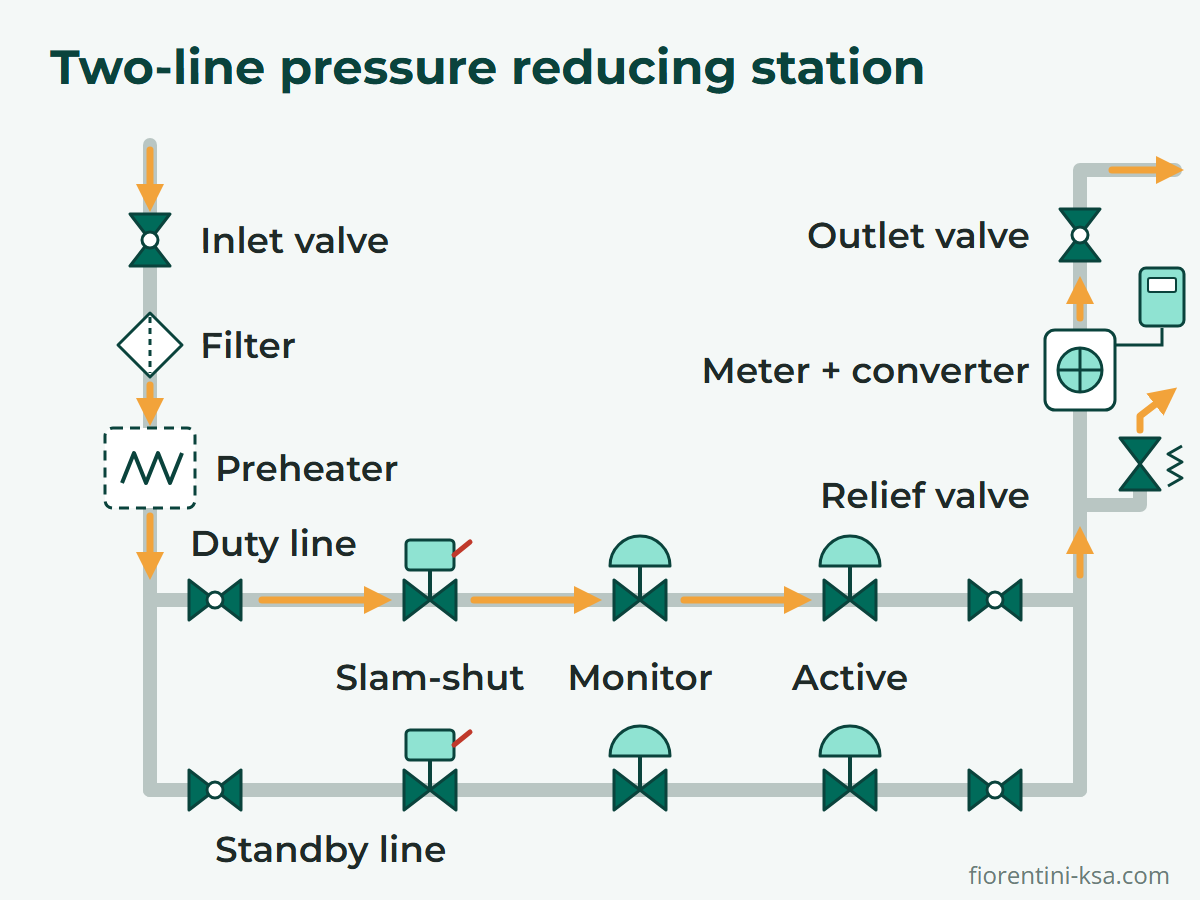
The diagram shows a typical two-line layout.
Inlet valve and insulating joint
A ball valve isolates the station from the pipeline. Trunnion ball valves suit high-pressure inlets, and their top-entry design lets the ball be removed in line. An insulating joint electrically isolates the station so that the pipeline's cathodic protection keeps working. On unmanned stations, a remotely operated inlet valve allows emergency isolation.
Filter and separator
Dust and welding slag must be kept away from regulators, meters and valves, so a filter comes next, plus a separator where liquids are expected. The HFA-HFB dry gas filter has a design pressure up to 100 bar, with 5-micron filtration as standard. A differential pressure gauge shows when the element needs changing. Filtration is often duplicated, with two filters in parallel or one per regulating line, so an element can be changed without stopping the supply.

Preheater
Where the pressure cut is large, a heat exchanger warms the gas before it reaches the regulators. Pietro Fiorentini's shell-and-tube units use hot water, superheated water or steam. Stations with small pressure drops may not need one.
Slam-shut valve, monitor and active regulator
On each line, three devices work together:
- Slam-shut valve: a safety shut-off device (EN 14382) that closes quickly when the monitored pressure leaves its set limits, high or low. The SBC 782 is rated up to 102 bar in sizes up to 10 inches, and an operator can also close it locally or remotely.
- Monitor regulator: a second regulator in series, normally upstream and set slightly higher. It takes over if the active regulator fails open.
- Active regulator: controls the outlet pressure in normal operation. The pilot-operated Reflux 819 covers 0.8 to 100 bar inlet and 0.3 to 74 bar outlet pressure, in sizes from 1 to 12 inches.
The guide to slam-shut, monitor and relief valves explains how their set points are staggered.
Relief valve
Downstream of the regulators, a small relief valve vents excess pressure caused by thermal expansion, pressure shocks or creep (minor leakage past a closed regulator). It is a token relief, not sized for a full regulator failure. The direct-operated VS/AM 58 is rated up to 100 bar in a 1-inch size.
Meter and volume converter
The IM-TM turbine meter covers 8 to 6,500 m³/h. The FioSonic multi-path ultrasonic meter handles more than 40,000 m³/h, with a design pressure up to 153 bar(a). A volume converter such as Modus, Modus Slim2 or the single-channel Modus Mini uses pressure and temperature inputs to convert the measured volume to base conditions. The guide to types of gas meters explains the choice.
Upstream of the regulators, the denser gas allows a smaller meter, clear of regulator disturbance. Downstream, the pressure is steady, but the meter needs enough straight pipe after the regulators. Keep ultrasonic meters well away from regulators, which are a main source of ultrasonic noise.
Outlet valve, bypass and odorizer
An outlet ball valve closes the station off from the network. EN 12186 also sets requirements for bypasses, which can use a bypass and throttling valve such as the VLM. Where gas is odorized, the odorizer usually sits at the city gate, often dosing odorant in proportion to flow.
Why stations have two regulating lines
A single regulating line is a single point of failure: a slam-shut trip or maintenance stops the supply. The usual remedy is two identical lines, each able to carry the full design flow. For example, GIS/E34, a UK and Irish specification for regulator modules up to 7 bar inlet, requires each stream to carry the design capacity at the minimum design inlet and maximum design outlet pressure.
One line is the duty line. The standby regulator is set slightly lower, so it stays closed while the duty line holds the pressure. If the duty line shuts, the outlet pressure falls to the standby set point and the standby line opens automatically.
A stream discrimination device, such as a non-return valve at each line outlet, ensures that a fault trips only the faulty line. Either line can also be isolated and serviced while the other runs.
Design considerations: sizing, velocity, noise and temperature
Sizing at the worst case
Size each line at the lowest inlet pressure and the highest flow, and check stable control at minimum flow. When a monitor sits in series with the active regulator, Pietro Fiorentini's sizing guidance is to take about 20 % off the active regulator's Cg. The gas pressure regulator guide explains Cg-based sizing.
Gas velocity and noise
High gas velocity causes erosion and noise. Pietro Fiorentini's regulator brochures give the speed at the outlet flange as:
V = 345.92 × (Q / DN²) × (1 − 0.002 × Pd) / (1 + Pd)
Here V is in m/s, Q is the flow in Stm³/h, DN the regulator size in mm and Pd the outlet pressure in barg. For example, 5,000 Stm³/h at 4 barg leaves a DN 100 outlet at about 34 m/s, but a DN 150 outlet at about 15 m/s. GIS/E34 caps velocity at 20 m/s for unfiltered inlet gas and 40 m/s for filtered gas in the outlet header. India's PNGRB rules permit the same figures, within the manufacturer's limits.
GIS/E34 also limits the average noise exposure level 1 m from the module to 85 dBA, the recommended limit in Pietro Fiorentini's silencer charts. A silencer built into the regulator absorbs noise where it is generated. The same velocity and noise checks apply wherever control valves throttle the gas.
Temperature and preheating
Gas cools as it expands through a regulator. For natural gas, this Joule–Thomson effect is roughly 0.4–0.5 °C per bar of pressure drop. At about 0.45 °C per bar, a cut from 70 to 16 bar chills the gas by about 24 °C.
Gas arriving at 15 °C would leave at about −9 °C, risking hydrates, condensation, equipment faults and pipework colder than its design temperature. A preheater upstream of the regulators prevents this.
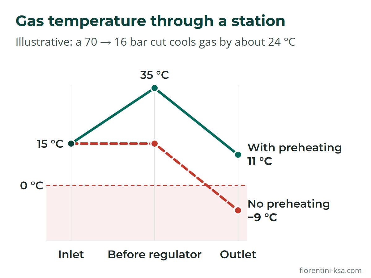
Size the heater for the worst case: the coldest inlet gas, the largest pressure cut and the highest flow. Hydrogen blends cool less, so they need less preheating.
In Saudi Arabia and the GCC, heat and dust need attention too. Compare each device's temperature rating, often −20 °C to +60 °C for Pietro Fiorentini regulators, with conditions inside sun-exposed cabinets. Use enclosures that keep out sand and dust, and clean sand and welding debris out of new pipework before start-up.
Skid, cabinet or building: how stations are built
Many stations arrive as packages, pre-piped on a steel skid or inside a cabinet, which shortens installation in the field. Cabinets add protection against tampering and climate. EN 12186 also covers other housings, including underground stations in a pit or a buried vessel.
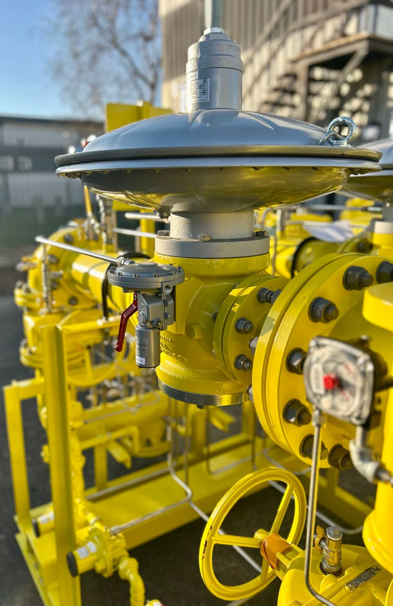
Electrical devices must suit the hazardous-area zone; the Modus converter, for example, is suitable for ATEX Zone 0. Drain and vent points let each section be depressurized for maintenance. The 2025 edition of EN 12186 adds requirements for smart equipment and information security.
Commissioning and maintenance
Before gas-in, the station is strength- and tightness-tested, following procedures such as those in EN 12327. During commissioning, open valves slowly and confirm that each regulator settles at its set point, or slightly above it at zero flow. Check slam-shut trips and relief settings, test for leaks, and confirm that the standby line takes over.
Maintenance intervals follow national regulations or the operator's procedures. Otherwise, Pietro Fiorentini's manuals base them on gas quality and pipe cleanliness. Inspections are more frequent after the first start-up, when new pipework may not yet be clean. Routine checks cover filter differential pressure, set points, lock-up, slam-shut trips and leaks.
How Pietro Fiorentini can help
Pietro Fiorentini Saudi Industry in Al Khobar supplies station components, from ball valves and filters to slam-shut valves, regulators, meters and volume converters. Its gas network solutions include complete skid-mounted and cabinet stations, and its services cover engineering, commissioning, maintenance, spare parts and training.
Planning a pressure reducing or metering station? Share the inlet pressure range, outlet set point, peak and minimum flows and any metering requirements, and our engineers will propose a station layout. Contact our engineers.
Frequently asked questions
What is the difference between a pressure reducing station and a PRMS?
A pressure reducing station lowers and controls gas pressure and protects the downstream network. A pressure reducing and metering station (PRMS) also measures the gas, usually with a meter and a volume converter, for billing or network management. EN 12186 covers the pressure control function and EN 1776 the measuring system.
What is a city gate station?
A city gate station is where a local distribution network takes gas from a transmission pipeline. It cuts the pressure to distribution levels, usually meters the gas for custody transfer and often adds odorant so that leaks can be detected. The large pressure cut frequently calls for preheating.
Why is gas preheated before pressure reduction?
Expanding gas cools: natural gas loses roughly 0.4–0.5 °C for every bar of pressure drop. A large cut can take it below 0 °C, risking hydrates, condensation, equipment faults and pipework colder than its design temperature. Whether a heater is needed upstream of the regulators depends on the inlet gas temperature and the size of the cut.
Why do pressure reducing stations have two regulating lines?
Two identical lines keep gas flowing when one line trips on a fault or is isolated for maintenance. Each line can carry the full design flow. The standby regulator is set slightly below the duty regulator, so it stays closed in normal operation and opens automatically if the duty line closes.
Which standards apply to gas pressure reducing stations?
EN 12186 sets functional requirements for gas pressure control stations up to 100 bar inlet pressure, and EN 1776 covers gas measuring systems. Components have their own standards, such as EN 334 for regulators and EN 14382 for slam-shut devices. National regulations and operator specifications apply on top.
References
- EN 12186:2025 Gas pressure control stations for transmission and distribution – Functional requirements – Swedish Institute for Standards (SIS)
- EN 1776:2025 Gas measuring systems – Functional requirements – Estonian Centre for Standardisation and Accreditation (EVS)
- GIS/E34:2021 Specification for the procurement of pressure regulating modules with inlet pressures above 75 mbar but no greater than 7 bar – Energy Networks Association
- Technical Standards and Specifications including Safety Standards for City or Local Natural Gas Distribution Networks Regulations, 2008 (as amended) – Petroleum and Natural Gas Regulatory Board, India
- Joule-Thomson effect in case of mixtures of natural gas and hydrogen – Danish Gas Technology Centre
- Reflux 819/FO technical brochure – Pietro Fiorentini