

An ultrasonic gas meter measures flow by timing pulses of sound sent through the gas, once with the flow and once against it. The time difference gives the gas velocity, and the bore area turns velocity into volume flow. With no moving parts and low pressure loss, multipath ultrasonic meters serve transmission pipelines, storage facilities, distribution networks and large end users. This guide explains the principle, meter designs, accuracy, applications, installation and diagnostics, including hot, dusty sites in Saudi Arabia and the GCC.
Key takeaways
- The meter compares the transit times of sound pulses sent with and against the flow.
- Multipath meters tolerate distorted flow profiles better than single-path designs.
- Under OIML R 137, a class 1 meter must stay within ±1 % from Qt to Qmax at type evaluation.
- Straight pipe, flow conditioning and distance from noisy regulators strongly affect field accuracy.
- Speed of sound, gain and signal-to-noise diagnostics show the meter's health in service.
In this article
How an ultrasonic gas meter works
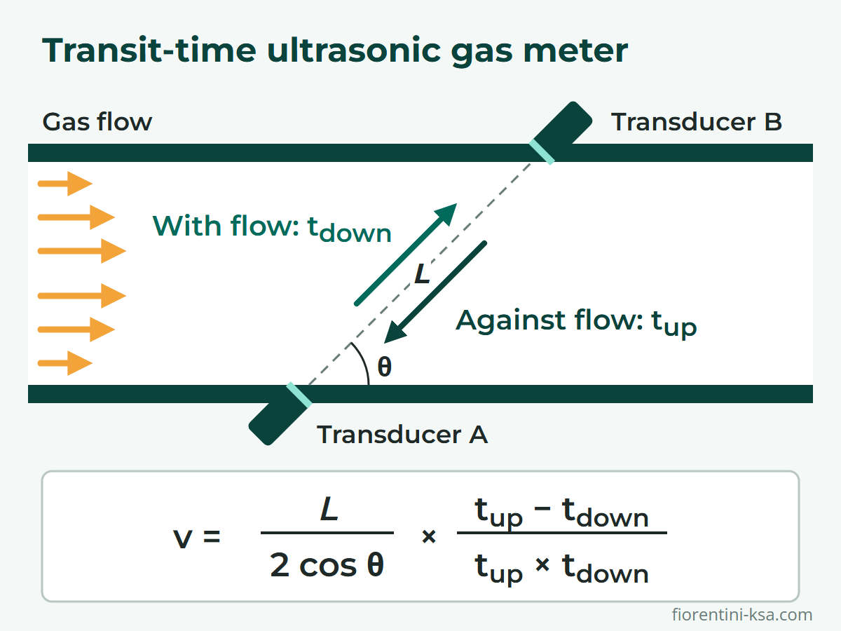
Inside the meter body, pairs of transducers send sound pulses to each other across the pipe at an angle to its axis. Each transducer both transmits and receives. A pulse sent downstream is carried by the gas and arrives sooner; a pulse sent upstream along the same path is slowed and arrives later. ISO 17089 and AGA Report No. 9 both cover this transit-time method.
Call L the path length and θ the angle between the path and the pipe axis. With t_up and t_down the transit times against and with the flow, the average gas velocity along the path is:
v = L / (2 cos θ) × (t_up − t_down) / (t_up × t_down)
The speed of sound cancels out, so pressure, temperature or composition changes that alter it do not enter the velocity calculation. The two times also give the speed of sound itself, c = L / 2 × (t_up + t_down) / (t_up × t_down), a key diagnostic.
As an illustration, take a 300 mm bore, a 45° diametral path (L ≈ 0.42 m) and a speed of sound of 420 m/s. At a gas velocity of 10 m/s, each pulse crosses in about 1 millisecond, and the pulse sent against the flow arrives about 34 microseconds later. At 0.5 m/s the difference is only 1.7 microseconds, so measuring that velocity to within 0.2 % takes a timing resolution of about 3 nanoseconds.
Each path gives the average velocity along one line. The meter estimates the mean velocity over the bore and multiplies it by the bore area to give volume flow at line conditions. A flow computer or volume converter then corrects this to base conditions, as explained in the guide to smart gas meters and volume converters.
Single-path vs multipath ultrasonic meters
A single-path meter measures along one line and converts the reading into a mean velocity with a profile correction factor. That factor depends on the Reynolds number and assumes a fully developed, swirl-free profile, which bends, headers and valves upstream disturb. Single-path meters therefore need longer, cleaner inlet runs. Even then, the AGA technical note appended to Report No. 9 judges them unlikely to match multipath performance.
AGA Report No. 9 defines a multipath meter as one with at least two independent transducer pairs. Chordal paths cross the pipe at different distances from the center, and the meter weights and sums their velocities to estimate the mean. Several paths bring:
- better tolerance of asymmetric and swirling profiles;
- profile and symmetry diagnostics from the ratios between paths;
- redundancy: a meter that loses a path should raise an alarm and keep measuring, although accuracy will likely be reduced.
Accuracy, calibration and standards
Accuracy is stated as a maximum permissible error (MPE). OIML R 137, the international recommendation for gas meters, defines three accuracy classes. It splits the flow range at the transitional flow rate Qt, with wider limits between the minimum flow Qmin and Qt.
| Accuracy class | Qmin ≤ Q < Qt | Qt ≤ Q ≤ Qmax |
|---|---|---|
| 0.5 | ±1 % | ±0.5 % |
| 1 | ±2 % | ±1 % |
| 1.5 | ±3 % | ±1.5 % |
These limits apply at type evaluation and initial verification. For subsequent and in-service verification, R 137 lists limits twice as wide, which national authorities may choose to apply.
For custody transfer, where gas changes ownership, AGA Report No. 9 has required traceable flow calibration since its 2007 edition. The meter is tested at several flow rates, and calibration adjustment factors then remove the indicated bias, with a second set for reverse flow.
The main standards are:
- ISO 17089-1:2019: transit-time meters for custody transfer and allocation, including calibration, diagnostics and installation.
- ISO 17089-2:2012: transit-time meters for industrial applications.
- AGA Report No. 9: the American Gas Association's performance-based specification for multipath meters. This guide quotes its 2007 second edition; later editions followed in 2017 and 2022.
- OIML R 137-1&2: metrological requirements and tests for gas meters of any measuring technology.
- EN 14236:2018: battery-powered ultrasonic domestic meters up to 0.5 bar and 10 m³/h.
Advantages and limitations
The main strengths:
- No moving parts: no rotor or bearings to wear or lubricate.
- Negligible pressure loss: a full-bore body has no significant protrusions or constrictions.
- Wide rangeability: a high turndown ratio (Qmax/Qmin), with the certified range set by model and size.
- Bidirectional measurement: one meter can measure flow in either direction when configured for it.
- Self-diagnostics: support for condition-based maintenance and recalibration.
The main limitations:
- Flow profile: asymmetry can persist for 50 pipe diameters or more downstream of a fitting, and swirl for 200 or more.
- Ultrasonic noise: regulators and control valves can mask the signal. Low-noise valve trims are a particular concern, because they shift acoustic energy above 50 kHz, into the ultrasonic range.
- Deposits: a layer on the wall reduces the bore and makes the meter over-read; deposits on transducer faces can weaken the signal.
- Minimum pressure: transducers need enough gas density to couple sound into the gas.
- Low velocity: below about 0.6 m/s, thermal gradients across the pipe add uncertainty.
Where ultrasonic gas meters are used
Typical locations include:
- Transmission and fiscal metering stations, with conditioned, flow-calibrated meter runs.
- City gates and district stations, where compact multipath meters fit smaller lines.
- Power plants, industry and storage sites, where low pressure loss and diagnostics help.
- Homes and small businesses, with battery-powered ultrasonic domestic meters.
Installing an ultrasonic gas meter
Because the meter measures velocity, it needs a predictable flow profile at its inlet. AGA Report No. 9 recommends flow conditioning for custody transfer and asks manufacturers to back their recommended layouts with test data.
Where no tested layout exists, its 2007 edition offers a conservative default. Upstream, it uses 10 nominal diameters (D) of straight pipe, a qualified (performance-tested) flow conditioner and 10 D more; downstream, 5 D. Bidirectional runs repeat the upstream arrangement on both sides.
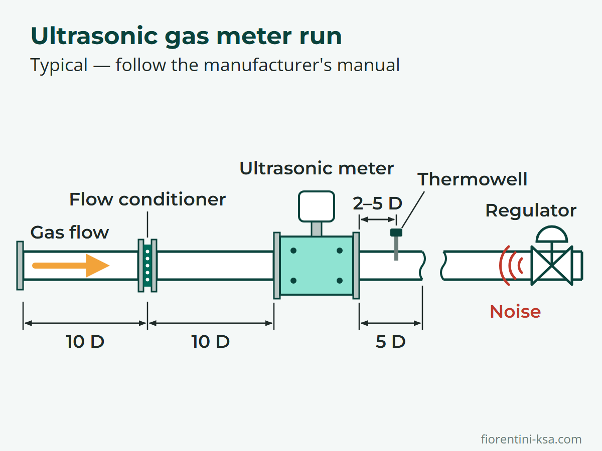
Manufacturer-tested layouts can be shorter, but each applies only to the configuration it was tested with. Under OIML R 137, a meter approved only for specific piping arrangements may be installed only in those, so follow the manual and approval certificate.
Four further details matter:
- Install as calibrated: if the meter was calibrated with its own spools and conditioner, reassemble them with the flange alignment marked at calibration.
- Avoid steps and protrusions: match the upstream pipe bore to the meter within 1 %, and let no gasket protrude more than 1 % of the diameter.
- Place the thermowell downstream: 2 to 5 D from the meter's outlet flange, or 3 to 5 D in bidirectional service.
- Keep regulators away, preferably downstream: upstream noise sources do more harm, and distance and fittings between source and meter add attenuation. Agree the layout with the manufacturer at design stage.
At commissioning, follow the manufacturer's procedure and raise pressure slowly, because rapid pressurization or blowdown can damage transducers. Then record zero-flow readings and per-path diagnostics at known gas composition as a baseline.
Hot, dusty and remote sites
Sites in Saudi Arabia and the GCC add three checks:
- Heat: AGA Report No. 9 recommends considering a sun shield for meters and electronics in direct sunlight. Check ambient ratings too: the FioSonic is rated −40 °C to +60 °C ambient (−25 °C to +55 °C for custody transfer), with gas temperatures from −30 °C to +80 °C, and the FioSonic Mini −25 °C to +55 °C ambient for custody transfer (−40 °C to +60 °C for non-custody use).
- Sand and debris: where sand, dirt or mill scale may reach the meter, fit a filter such as the HFA-HFB dry gas filter and monitor its differential pressure. Outside the pipe, choose an electronics enclosure rated for windblown dust.
- Distance: trend diagnostics remotely so that changes at unmanned sites show up early, and ask whether transducers can be replaced without depressurizing the meter run.
Ultrasonic meter diagnostics
Diagnostic indicators show whether the measurement can be trusted. AGA Report No. 9 advises recording a baseline at calibration and start-up, then judging later readings against it.
| Indicator | What it shows | A change can point to |
|---|---|---|
| Speed of sound | Measured value vs. one calculated from composition, pressure and temperature (AGA Report No. 10) | Timing or geometry error, wrong composition data |
| Speed-of-sound ratio | Agreement between paths, normally very close to 1.0 | A process problem or poor signal detection on one path |
| Gain | Amplification needed to receive each signal | Deposits on transducer faces, liquids |
| Signal-to-noise ratio | Signal quality per transducer | Noise from control valves or regulators |
| Performance | Share of accepted pulses per path | Noise, very high velocity, strong turbulence |
| Profile and turbulence factors | Velocity ratios between paths and their scatter | Upstream disturbance, wall deposits |
Gain and signal-to-noise values also vary with pressure, composition and velocity, so compare readings at similar conditions, using the manufacturer's limits. AGA Report No. 9 also asks the manufacturer for a field verification procedure, such as zero-flow, speed-of-sound and internal-inspection checks.
How Pietro Fiorentini can help
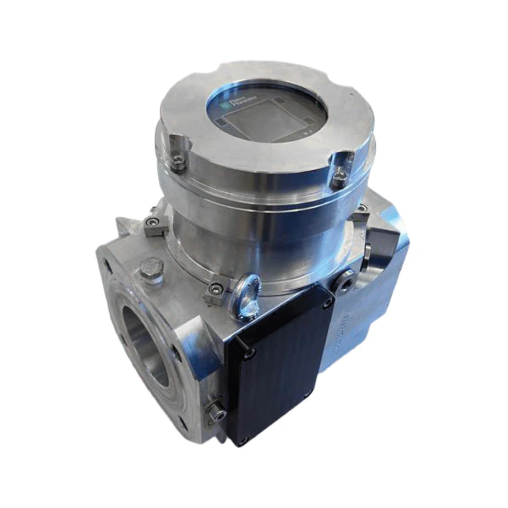
Pietro Fiorentini Saudi Industry offers two ultrasonic gas meters for fiscal and custody transfer applications. Both use multi-path chordal technology with real-time diagnostics and built-in redundancy, and both accept natural gas–hydrogen blends up to 30 %.
- FioSonic: 2 to 30 inches in the three-path version and 3 to 30 inches in the four-path version, design pressure up to 153 bar(a), forged steel body; for high-pressure transmission, medium-pressure distribution, gas storage, power generation and fiscal metering.
- FioSonic Mini: 3 and 4 inches, 20 bar(a) design pressure, aluminum body, class 1 accuracy, MID (EU Measuring Instruments Directive) and OIML certification for custody transfer; for distribution networks, city gates, district stations and commercial users.
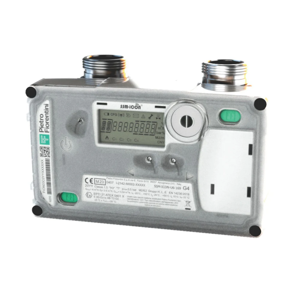
For conversion to base conditions, the Modus PTZ volume converter takes pulse inputs from primary gas meters plus pressure and temperature. For homes and commercial users on low-pressure networks, the SSM-iCON smart meter also measures ultrasonically, at class 1.5 from 0.04 to 6 m³/h.
Fiscal metering systems for custody transfer belong to the gas networks range, and the services team supports engineering, commissioning, maintenance and PF Gas Academy training.
Planning an ultrasonic metering run? Send us your pipe size, pressure range, flow rates and station layout. Our engineers will help you select the meter and plan the meter run. Contact our engineers.
Frequently asked questions
How accurate is an ultrasonic gas meter?
It depends on the accuracy class, calibration and installation. Under OIML R 137, a class 1 meter must stay within ±1 % from Qt to Qmax and ±2 % below Qt at type evaluation; class 0.5 halves those limits. Flow calibration corrects the meter's bias in the laboratory. In service, disturbed profiles, noise and deposits can still shift readings, so trend the diagnostics.
Does an ultrasonic gas meter need a flow conditioner?
For custody transfer, usually yes. AGA Report No. 9 recommends flow conditioning for custody transfer, to minimize flow distortion and give a basis for the metering-package design. It also accepts manufacturer layouts without a conditioner when test data support them. In every case, follow the layouts in the meter's manual and approval certificate.
Can an ultrasonic gas meter measure flow in both directions?
Yes. Transit-time meters are inherently bidirectional, but specify it when ordering so the meter is configured for it. Reverse flow gets its own calibration factors and is either recorded separately or subtracted, and the inlet piping rules apply to both ends. Under OIML R 137, a meter marked as bidirectional must meet its error limits in each direction.
How often should an ultrasonic gas meter be recalibrated?
No universal interval exists: AGA Report No. 9 leaves the decision to the parties using the meter. Recalibration can be calendar-based or condition-based, driven by diagnostics, usage and line conditions. National rules or contracts may set fixed intervals. Comparing speed of sound, gain and profile data with the calibration baseline shows when a meter needs cleaning or recalibration.
Ultrasonic or turbine gas meter: which should I choose?
Both are velocity meters used for custody transfer, so compare line size, flow range, flow direction and maintenance. An ultrasonic meter has no moving parts, measures both ways and diagnoses itself; a turbine meter's rotor runs on bearings that wear. The IM-TM turbine meter covers 2 to 12 inches, the FioSonic 2 to 30 inches. For wider comparisons, see types of gas meters and rotary vs turbine gas meters.
References
- ISO 17089-1:2019 Ultrasonic meters for gas – Part 1: Meters for custody transfer and allocation measurement – ISO
- ISO 17089-2:2012 Ultrasonic meters for gas – Part 2: Meters for industrial applications – ISO
- AGA Report No. 9, Measurement of Gas by Multipath Ultrasonic Meters, Second Edition (2007) – American Gas Association, via Public.Resource.Org
- OIML R 137-1&2:2012 Gas meters, including Amendment 2014 – OIML
- BS EN 14236:2018 Ultrasonic domestic gas meters – BSI