

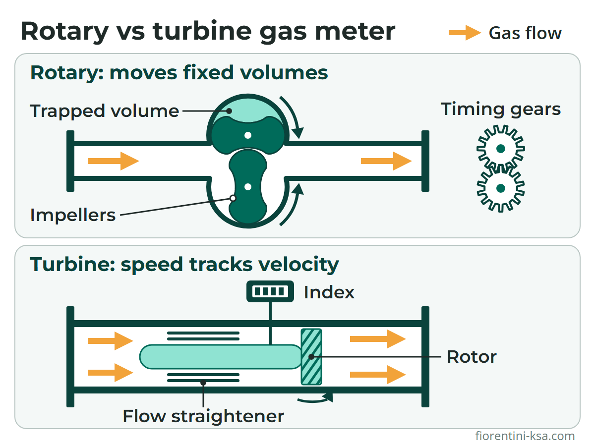
A rotary gas meter traps and counts fixed volumes of gas between two impellers. A turbine gas meter infers volume from the speed of a bladed rotor. That difference shapes most of the rotary vs turbine gas meter decision.
Rotary meters stay accurate at very low flows, tolerate fluctuating loads and need no straight pipe. Turbine meters handle larger flows and higher pressures, but they need a conditioned inlet and are sensitive to pulsating flow.
Key takeaways
- Rotary meters move fixed volumes; turbine meters infer volume from rotor speed.
- At the same G-size and low pressure, the IM-RM's minimum flow is up to about eight times lower than the IM-TM's.
- Rapid pulsations and on/off flow can make a turbine meter over-register.
- Turbine meters cover higher flows and pressures: up to 6,500 m³/h and 100 bar for the IM-TM.
- Turbines need straight pipe or conditioning; rotary meters need none, but a jam stops the gas.
In this article
- How rotary and turbine gas meters work
- Rangeability and low-flow performance
- Pulsating and intermittent flow
- Installation: straight pipe, filtration and start-up
- Lubrication and maintenance
- Rotary vs turbine gas meter: side-by-side comparison
- How Pietro Fiorentini can help
- Frequently asked questions
How rotary and turbine gas meters work
Both are mechanical meters that measure gas volume at line conditions, in actual cubic meters. Pietro Fiorentini's rotary gas meters and turbine gas meters both drive a magnetically coupled index with low-frequency pulse outputs.
Rotary meters: counting fixed volumes
A rotary meter is a positive displacement meter. Two figure-eight impellers turn in opposite directions inside a rigid measuring chamber. Timing gears keep them in step, and small clearances seal them without contact.
Each turn carries pockets of gas from inlet to outlet, so the volume passed is proportional to the revolutions. In the IM-RM range, this volume per revolution, the cyclic volume, runs from 0.18 to 5.97 dm³.
Turbine meters: inferring volume from velocity
A turbine meter is a velocity, or inferential, meter. Gas passes a straightening section that removes swirl, then drives a rotor with helical blades. Rotor speed is proportional to gas velocity, so counting revolutions gives the volume.
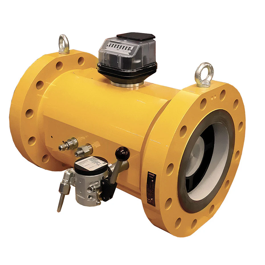
The IM-TM has a multi-stage flow conditioner built into its body. Its bearings and gears sit upstream of the rotor, away from the dirt that collects around it.
Rangeability and low-flow performance
Rangeability, or turndown, is the ratio of maximum to minimum flow, Qmax/Qmin, for one meter size. Both meters here are class 1.0, with maximum permissible errors of ±2 % from Qmin to the transitional flow Qt and ±1 % from Qt to Qmax.
A rotary meter's low-flow limit is the gas slipping through its clearances, which the IM-RM impeller profile minimizes. A turbine meter's limit is fluid drag and mechanical friction at low rotor speeds (AGA Report No. 7).
The G-number is a size code; in both datasheets, Qmax is about 1.6 times the G-number. Where the IM-RM (G10 to G650) and IM-TM (G40 to G4000) sizes overlap:
| Size | Qmax | IM-RM rotary Qmin | IM-TM turbine Qmin |
|---|---|---|---|
| G100 | 160 m³/h | 1 m³/h (1:160) | 8 m³/h (1:20) |
| G250 | 400 m³/h | 2.5 m³/h (1:160) | 20 m³/h (1:20) |
| G650 | 1,000 m³/h | 6.5 m³/h (1:160) | 50 m³/h (1:20) |
These are standard capacity-table values (IM-TM custody transfer series; lowest-Qmin IM-RM row per size); other pipe sizes and versions differ.
Pressure helps the turbine. Its maximum actual flow is fixed by rotor speed, but its minimum flow falls as gas density rises. AGA Report No. 7 puts the gain in range at roughly the square root of the absolute pressure ratio, so ask for Qmin at your operating pressure.
Size both types in actual m³/h. For example, 2,000 m³/h at base conditions is only about 250 m³/h at 7 bar(g), before temperature and compressibility corrections. That calls for a G250 meter, not one sized for 2,000 m³/h. For load growth, one 6-inch IM-TM body accepts cartridges with a Qmax of 650, 1,000, 1,600 or 2,500 m³/h.
Pulsating and intermittent flow
Turbine meters follow slow load changes well, but not rapid cycles. AGA Report No. 7 notes that pulsations from compressors and fast-cycling regulators generally make a turbine meter over-register; dampeners between the source and the meter are an effective cure.
The IM-TM manual also lists pulsating and intermittent flow as causes of high readings, with two remedies: reduce the pulsations or change the meter type.
A rotary meter displaces a fixed volume per turn, and Pietro Fiorentini states that fluctuating flow does not affect its accuracy. That suits cycling loads, such as burners that switch on and off.
However, the impellers themselves create small pressure pulsations, proportional to the pressure drop and rotor speed. Their effect increases with pressure, and resonance can affect the linearity of the calibration curve and nearby regulators. Larger IM-RM sizes come in Twin versions, whose two impeller pairs run out of phase so that pulsations cancel and noise drops.
Installation: straight pipe, filtration and start-up
Turbine meters are sensitive to inlet flow disturbances. OIML R 137 applies flow-disturbance tests to turbine meters, not rotary ones, and the type approval certificate states any straight length or conditioner required.
The IM-TM manual cites an EN 12261 minimum of 2 DN of straight pipe upstream. It recommends 5 DN upstream and 3 DN downstream, and perforated-disc flow rectifiers where a regulator is nearby. AGA Report No. 7 also advises keeping regulators and throttling valves away, especially upstream.
Rotary meters need no straight runs; the IM-RM manual sets none, though its rotor axes must stay horizontal. For both types:
- Filter the gas: the manuals recommend a 100 µm filter for the IM-RM and 160 µm for the IM-TM. Add a temporary 250 µm strainer for a new rotary installation's first weeks.
- Mount it level: within 5 mm/m in both directions, free of stress from misaligned pipes.
- Avoid low points, where liquids and dirt collect. Keep lubricated plug valves away from a turbine inlet, because excess grease can foul the rotor.
- Pressurize slowly: both manuals set a maximum of 0.35 bar/s (35 kPa/s). Surges during pressurizing, blowdown or purging can severely damage a turbine rotor.
- Plan for a jam: seized rotary impellers stop the gas, so add a bypass or a Twin IM-RM with an internal bypass.
- Record the pressure drop at several flow rates at commissioning; a later rise points to deposits, friction, wear or contaminated oil. In turbines it also rises with gas density and the square of flow (AGA Report No. 7), so compare readings at similar pressure and flow.
Hot, dusty and remote sites
Both meters are rated for gas temperatures up to +55 °C (the IM-TM's ambient rating reaches +65 °C). Their index housings are UV-resistant, but both manuals require installation away from direct sunlight and weather, so outdoor meters need a canopy or shelter.
Sand and dust make filtration critical. The HFA-HFB dry gas filter is designed for up to 100 bar, with 5 µm elements as standard. Filters for low pressure are designed for up to 10 bar, with 5 or 50 µm elements depending on the model. Choose an element at least as fine as the meter manual asks, and monitor its differential pressure.
At remote sites, the half-yearly pressure-drop and totalization checks can run on a remote system that raises alarms at preset thresholds.
Lubrication and maintenance
Both meters ship without oil; fill it after installation and before commissioning.
- Rotary: check the IM-RM sight glass at least twice a year and top up when the oil is about 3 mm low. Change the oil at least every seven years, or at once if moisture raises the level by over 3 mm.
- Turbine: IM-TM bearings must stay clean and lubricated: oil is added with the supplied pump while the meter runs, and the lubrication system flushes dirty oil away. The manual calls for oiling quarterly, except during extended low-flow periods. AGA Report No. 7 adds that high flows, high gas temperatures or dirty gas may need more frequent oiling.
Every six months, both manuals call for checking the pressure drop against its commissioning value, totalization, noise and visible damage. For turbines, AGA Report No. 7 adds a spin time test: the rotor's run-down time, tracked against the manufacturer's value and past records, indicates mechanical friction.
The IM-TM manual allows a gradual, pulsation-free 120 % Qmax overload for under an hour; excessive overloading wears bearings and gears.
Rotary vs turbine gas meter: side-by-side comparison
Values are for the IM-RM and IM-TM; other models differ.
| Factor | Rotary (IM-RM) | Turbine (IM-TM) |
|---|---|---|
| Principle | Positive displacement | Velocity (inferential) |
| Flow range | 0.5–1,000 m³/h | 8–6,500 m³/h |
| Sizes | 1½–6 inch, G10–G650 | 2–12 inch, G40–G4000 |
| Design pressure | Up to 25 bar(g) | Up to 20 bar (aluminum) or 100 bar (steel) |
| Standard rangeability | Up to 1:200, by size | Up to 1:20, wider at high pressure |
| Maximum error | ±1 % from Qt, ±2 % below | ±1 % from Qt, ±2 % below |
| Pulsating or on/off flow | Tolerant; creates small pulsations | Can over-register |
| Straight pipe | None required | 2 DN minimum, 5 DN recommended |
| Lubrication | Oil level checked twice a year | Oil injected in service, typically quarterly |
| Typical uses | Commercial and industrial users, distribution | Transmission, power plants, heavy industry, distribution |
| Product standard | EN 12480 | EN 12261 |
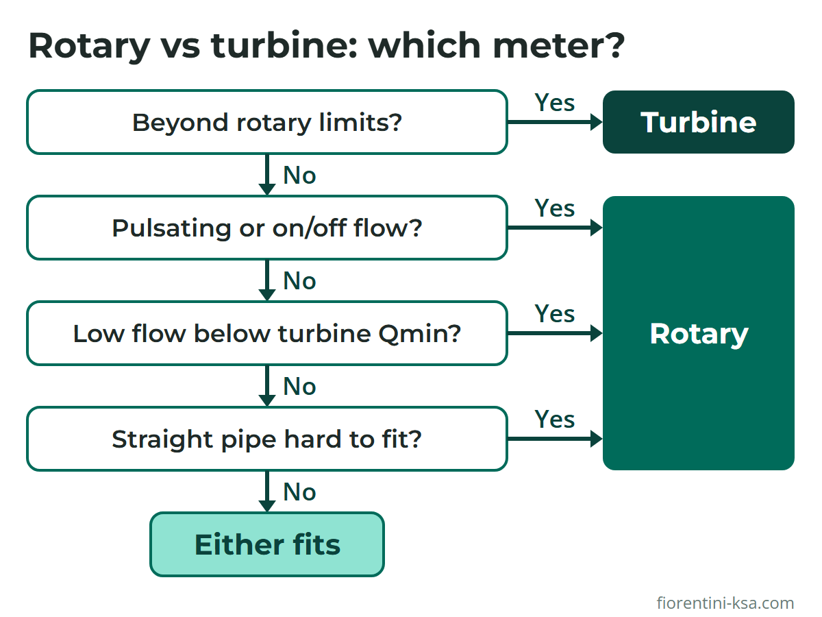
The flowchart turns these differences into a first check; a pulsating load above the rotary limits still needs dampeners ahead of the turbine. Where both meters fit, compare cost, space and your team's maintenance practice.
Standards that apply
- EN 12480:2025: rotary displacement gas meters with a mechanical index, up to 20 bar.
- EN 12261:2024: class 1.0 axial and radial turbine gas meters, up to 420 bar and 25,000 m³/h.
- OIML R 137-1&2:2012: accuracy classes, error limits and tests for gas meters of any technology; adopted in the GCC as GSO OIML R137-1&2:2013.
- AGA Report No. 7: performance, installation and maintenance of axial-flow turbine meters.
The IM-RM is designed to EN 12480 and OIML R 137, the IM-TM to EN 12261, and both are certified under the EU MID, PED and ATEX directives.
How Pietro Fiorentini can help
Pietro Fiorentini Saudi Industry supplies both technologies from its gas meter range. The IM-RM and the CT series of the IM-TM are approved for custody transfer (MID). Both are hydrogen-ready for natural gas–hydrogen blends, with dedicated 100 % hydrogen versions.
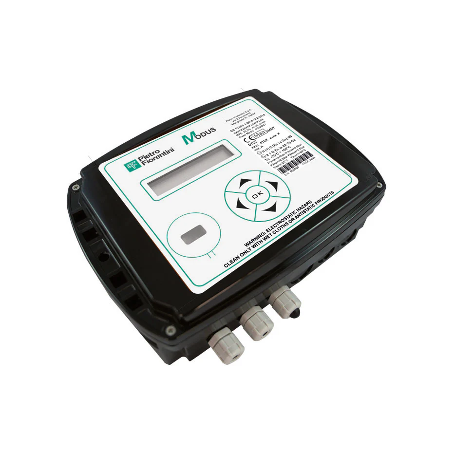
A volume converter such as Modus or Modus Mini corrects the meters' measured volume to base conditions. Modus handles up to two PTZ channels, is MID certified, suits ATEX Zone 0 areas and reports to SCADA systems. The guide to smart gas meters and volume converters explains the conversion.
For a wider view, see types of gas meters; for flows above the turbine range, see the ultrasonic gas meter guide. Pietro Fiorentini services cover engineering, commissioning, maintenance, spare parts and PF Gas Academy training.
Not sure which meter fits your load? Send us your minimum and maximum flows, operating pressure, load pattern and available piping space. Our engineers will recommend a rotary or turbine meter and its size. Contact our engineers.
Frequently asked questions
What is the difference between a rotary and a turbine gas meter?
A rotary meter is a positive displacement meter: its two impellers trap fixed volumes of gas, so each revolution passes a known volume. A turbine meter is a velocity meter whose bladed rotor turns in proportion to gas velocity. Rotary meters suit low and fluctuating flows; turbines suit large, steady flows and higher pressures.
Which is more accurate, a rotary or a turbine gas meter?
Within their rated ranges, they are comparable. The IM-RM and IM-TM are both class 1.0, with maximum permissible errors of ±1 % from Qt to Qmax and ±2 % below Qt. The rotary meter holds that accuracy to much lower flows, while a turbine's accuracy depends more on inlet piping, pulsation and bearing condition.
Do rotary and turbine gas meters need straight pipe?
Rotary meters do not, and OIML R 137 does not apply flow-disturbance tests to them. Turbine meters do. The IM-TM manual cites an EN 12261 minimum of 2 DN upstream and recommends 5 DN upstream and 3 DN downstream. AGA Report No. 7 recommends 10 diameters upstream, including a flow conditioner, unless the meter has integral conditioning.
How does pulsating flow affect a turbine gas meter?
A turbine rotor follows slow load changes but not rapid cycles from compressors or fast-cycling regulators. AGA Report No. 7 states that such pulsations generally cause over-registration, and that dampeners between the source and the meter are an effective fix. Where pulsation or on/off flow cannot be avoided, a rotary meter is often the better choice.
What happens if a rotary gas meter jams?
The impellers seal the measuring chamber, so seized impellers stop the gas flow. For a critical supply, add a valved bypass or a Twin IM-RM, whose internal bypass opens above a factory-set pressure loss. Good filtration helps prevent a jam, and half-yearly pressure-drop checks reveal dirt and wear early.
References
- OIML R 137-1&2:2012 Gas meters, including Amendment 2014 – International Organization of Legal Metrology (OIML)
- EN 12480:2025 Gas meters – Rotary displacement gas meters – Swedish Institute for Standards (SIS)
- EN 12261:2024 Gas meters – Turbine gas meters – SIS
- AGA Report No. 7, Measurement of Natural Gas by Turbine Meters (2006) – American Gas Association, via Public.Resource.Org
- IM-RM rotary gas meter technical brochure – Pietro Fiorentini
- IM-TM turbine gas meter technical brochure – Pietro Fiorentini